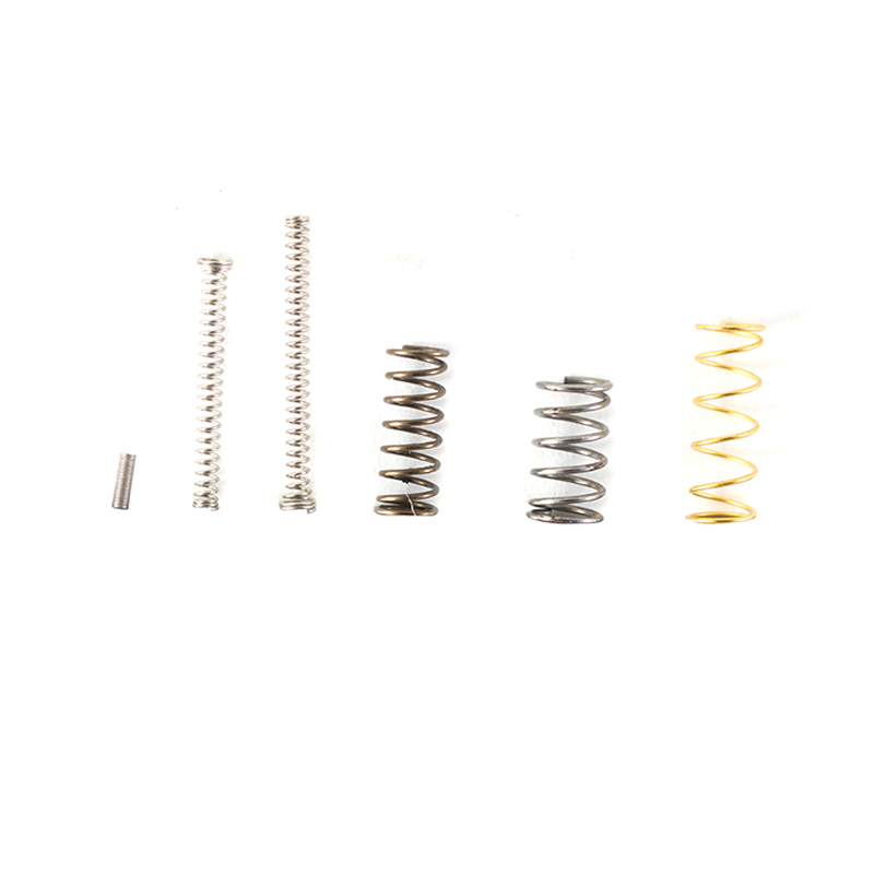
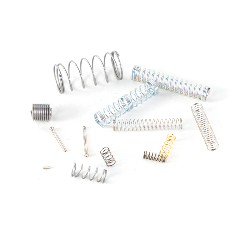
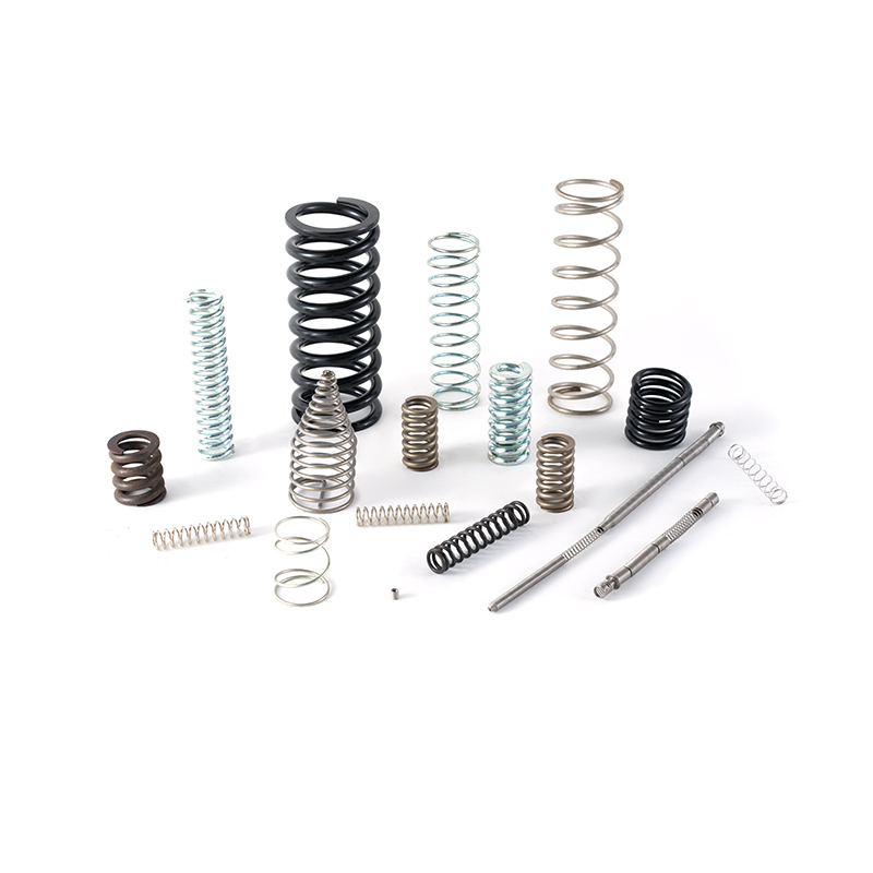
Spring selection decisions that seem straightforward on paper have a way of becoming complicated when a device fails in the field and the post-mortem points back to a spring that was technically within specification but wrong for the application. Engineers who have been through that experience know the gap between selecting a spring that meets a load requirement and selecting a spring that actually makes the system work correctly. A Precision Compression Spring is not defined by a single parameter — it is defined by the relationship between several parameters, with load capacity and spring rate sitting at the center of nearly every selection decision. Understanding how these two variables function, where they diverge, and how the application context determines which one deserves more attention is the foundation for avoiding specification errors before they reach production.
Defining the Two Parameters
Load Capacity Describes the Boundary, Not the Behavior
Load capacity refers to the maximum force a spring can absorb without undergoing permanent deformation. It is a structural limit — the point beyond which the spring wire yields plastically rather than elastically. Once a spring has been compressed past its load capacity, it does not return to its original free length. The coil geometry changes, the spring rate shifts, and the device it sits in behaves differently than designed.
In practical terms, load capacity governs safety margins. It answers the question: how much force can be applied before the spring is damaged? For engineers designing to a load capacity, the goal is to keep the operating force comfortably inside that boundary under all expected conditions — including overload scenarios, shock events, and manufacturing variation in the assembled system.
What load capacity does not tell you is how the spring behaves between zero and that limit. Two springs with identical load capacities can produce completely different forces at the same deflection — which is where spring rate becomes relevant.
Spring Rate Describes How the Spring Behaves Under Load
Spring rate — often expressed as the force required to compress the spring by a unit of length — quantifies how stiff a spring is. A spring with a high rate requires more force to compress by the same distance as a spring with a lower rate. This parameter is not about limits; it is about behavior throughout the operating range.
For any system where the spring is doing active work — providing a consistent return force to a valve, maintaining contact pressure in an electrical connector, controlling the actuation feel of a button — the spring rate is what determines whether the device functions as designed. The load capacity only becomes relevant if something is being asked of the spring that exceeds its design boundary.
These two parameters are connected but not interchangeable. Changing the wire diameter, coil diameter, or number of active coils changes both parameters, but not necessarily in the same direction or by the same proportion. A longer spring with the same wire diameter has a lower spring rate but can still reach the same load capacity at its solid height. A shorter spring of the same wire diameter has a higher rate but reaches its load capacity at a shorter deflection distance.
When Spring Rate Drives the Selection Decision
In systems where controlled force at a specific deflection is the design requirement, spring rate is the parameter that cannot be compromised. The load capacity needs to be adequate — but as long as it provides sufficient margin above the operating force, it is a secondary concern.
Applications where spring rate precision is the critical variable:
AUTO
Automation and Robotics
Actuators, end-effectors, and sensor mechanisms depend on predictable force-deflection relationships. A spring that delivers inconsistent force at a given position creates downstream positioning errors that accumulate in multi-stage systems.
VALV
Valve Actuation in Fluid Control Systems
The spring rate determines the cracking pressure of a valve and the force balance that controls flow at partial opening positions. Rate variation across a batch translates directly to variation in system behavior.
MED
Medical Device Mechanisms
Injection delivery systems, surgical instrument actuation, and diagnostic equipment all operate within narrow force windows. Rate tolerance is typically tight by design and needs to be maintained across the production life of the spring.
ELEC
Electrical Contact Springs
The contact force in a connector or switch is a function of the spring rate at the installed deflection. Low contact force increases resistance and creates reliability problems. Rate consistency across units ensures consistent contact pressure.
INST
Precision Instruments
Measurement equipment that uses spring-loaded elements for calibration or positioning depends on rate stability over time and across temperature changes.
Rate-Sensitive Applications
In all of these cases, the spring rate is not just a number in the specification — it is a parameter that directly drives system output. Specifying the correct rate and holding it to a tight tolerance is what separates a spring that makes the system work from one that creates systematic errors.
When Load Capacity Becomes the Governing Factor
Not all spring applications are about controlled force behavior. Some are primarily about containment — the spring provides a restoring force or a pre-load, but the primary concern is that the spring does not yield or fail under the forces it will encounter.
Situations where load capacity is the parameter that drives the specification:
IND
Heavy-Duty Industrial Equipment
Press tooling, clamping fixtures, and die cushion springs operate at high forces. The spring rate determines the force profile, but the structural integrity of the spring under those forces is what determines whether the equipment can be operated safely.
VIB
Vibration Isolation and Damping
Springs used to isolate machinery from vibration transmit dynamic forces that can spike well above the nominal static load. Load capacity needs to include adequate margin for these dynamic excursions.
SAFE
Safety-Critical Mechanisms
Springs in emergency stops, safety interlocks, and overload protection devices need to function reliably through the full range of forces they might encounter — including fault conditions that exceed normal operating levels.
FAT
High-Cycle Fatigue Applications
Even when operating well below the load capacity limit in any single cycle, springs in continuous high-cycle service experience progressive fatigue damage. The margin between operating force and load capacity affects how quickly fatigue accumulates and how long the spring lasts before a fatigue failure occurs.
The Parameters in Relationship: Why Both Matter Simultaneously
A common specification error is to focus on one parameter without checking whether the other is adequate. Both failure modes are worth understanding because they occur regularly:
Correct Rate, Inadequate Load Capacity
The spring delivers the right force at the design deflection, but the load capacity is marginal for the operating conditions. Under shock loading, thermal expansion, or manufacturing assembly variation that pushes the system to higher deflection, the spring yields. After yielding, the free length is shorter, the operating deflection is different, and the force at the design point is no longer what was specified. The system behavior drifts, often in ways that are subtle enough to escape notice until a downstream quality problem appears.
Adequate Load Capacity, Incorrect Rate
The spring survives everything asked of it structurally, but the force it delivers at the operating deflection is wrong. An overstiff spring in a tactile mechanism creates a heavy, unresponsive feel. An understiff spring in a valve does not close completely against the fluid pressure. In a precision instrument, the wrong rate shifts every measurement by a systematic offset. The spring lasts indefinitely — it just does not make the system work correctly.
Both Parameters Together
Getting both parameters right simultaneously requires understanding how they interact with the spring geometry, the material specification, and the operating conditions.
A Comparison of Parameter Priority by Application Type
How the priority between load capacity and spring rate shifts across different application categories:
| Application Type |
Primary Parameter |
Secondary Parameter |
Key Concern |
| Precision automation actuator |
Spring rate |
Load capacity |
Force consistency at position |
| Medical device mechanism |
Spring rate |
Load capacity |
Tight force tolerance across batch |
| Electrical contact spring |
Spring rate |
Load capacity |
Contact force repeatability |
| Heavy press tooling |
Load capacity |
Spring rate |
Structural survival under high force |
| Safety interlock mechanism |
Load capacity |
Spring rate |
Reliable function through fault conditions |
| High-cycle valve spring |
Both equally |
Fatigue life |
Rate consistency + structural durability |
| Instrument calibration spring |
Spring rate |
Load capacity |
Stable rate across temperature and time |
| Vibration isolation mount |
Load capacity |
Spring rate |
Dynamic overload margin |
Primary vs Secondary
This framing — primary versus secondary — does not mean the secondary parameter is unimportant. It means the design process starts from the primary parameter and then confirms the secondary is adequate, rather than the reverse.
How Tight Tolerances Affect Both Parameters
In a precision spring, tolerances on geometric parameters — wire diameter, coil diameter, free length, and active coil count — simultaneously affect both spring rate and load capacity. When a spring manufacturer holds tighter tolerances on wire diameter, for example, the variation in spring rate across the production batch narrows, but the load capacity distribution also tightens around its nominal value.
This interconnection has a practical consequence for specification. Specifying a tight rate tolerance on a spring without also specifying adequate control of the underlying geometric parameters that produce that rate can create a situation where rate tolerance is met on some units through compensating geometric variations that compromise load capacity margin on others.
A well-written spring specification for precision applications includes:
Wire Diameter Tolerance
Wire diameter tolerance matched to the rate tolerance needed.
Free Length & Solid Height
Free length tolerance and solid height confirmed against the load capacity requirement.
End Condition
End condition specified to ensure consistent active coil count across production.
Rate Testing
Rate tested under realistic deflection conditions, not just calculated from nominal geometry.
Load Capacity Confirmation
Load capacity confirmed against the combined effect of operating force and any expected overload conditions.
Working with a spring manufacturer who understands this interconnection — and who can document the relationship between geometric tolerances and parameter performance in their production process — prevents specification gaps that only appear in field failure analysis.
Material Selection and Its Effect on Both Parameters
Material selection affects both parameters through the material's elastic modulus and its yield strength. The elastic modulus determines the spring rate for a given geometry — a material with a higher modulus produces a stiffer spring from the same coil geometry than one with a lower modulus. The yield strength determines the load at which permanent deformation begins.
Higher Yield Strength Wire
Selecting a higher-yield-strength wire material for a spring that operates at a fixed geometric specification raises the load capacity without necessarily changing the spring rate, because the modulus and the geometry remain the same. This is a common strategy for improving load capacity margin without redesigning the spring geometry.
Different Modulus Material
Changing to a material with a different modulus — switching from carbon steel to stainless steel, for example — changes the spring rate for the same geometry, even if the yield strength is comparable. Engineers who substitute materials without accounting for modulus differences produce springs with a different rate than specified, even if all geometric tolerances are met.
Making the Selection Decision in Practice
When facing a spring selection or specification decision, a structured approach prevents the most common errors:
Step 1 — Operating Force Range
Define the operating force range. What force does the spring need to deliver, and at what deflection? This establishes the spring rate requirement.
Step 2 — Deflection Range
Define the deflection range. What is the total working stroke of the spring? This, combined with the rate, determines the force at the extremes of travel.
Step 3 — Overload Scenario
Identify the overload scenario. What is the highest force the spring might encounter — including manufacturing assembly errors, shock loading, and fault conditions? This sets the load capacity requirement.
Step 4 — Safety Margin
Calculate the safety margin. How much margin exists between the operating force and the load capacity? A narrow margin in a high-cycle or shock-prone application requires either a design change or a material upgrade.
Step 5 — Specify Tolerances
Specify tolerances that reflect functional requirements. If rate consistency drives system performance, specify rate tolerance tightly and confirm that the geometric tolerances needed to achieve it are included in the specification.
Step 6 — Confirm Material
Confirm the material selection against both parameters. Verify that the modulus supports the required rate and that the yield strength provides adequate load capacity margin.
This sequence works for straightforward applications. For more complex situations — multi-rate springs, springs subject to unusual environmental conditions, or applications where fatigue life is the limiting factor — additional analysis at each step is needed.
Specifying Springs That Perform Across Both Parameters
Load capacity and spring rate address different aspects of spring function, but a spring that fails on either dimension creates problems in the system it serves. The underlying precision that makes a spring perform reliably across both parameters — tight geometric tolerances, consistent material properties, controlled manufacturing processes — is not separable into two distinct categories. It is the same manufacturing quality that produces both correct rate behavior and adequate structural margin.
About the Manufacturer
For engineers and procurement teams specifying precision compression springs where both parameters need to be reliably controlled, Zhejiang Ningdeli Spring Co., Ltd. manufactures springs to close tolerances across wire diameter, coil geometry, and rate specifications, with documentation available on the relationship between manufacturing process and performance parameters. Reaching out to discuss your specific application requirements — force range, rate tolerance, material needs, and service conditions — is the practical way to confirm that the spring specification matches what the application actually demands.
 English
 中文简体
中文简体 русский
 Español
 Deutsch